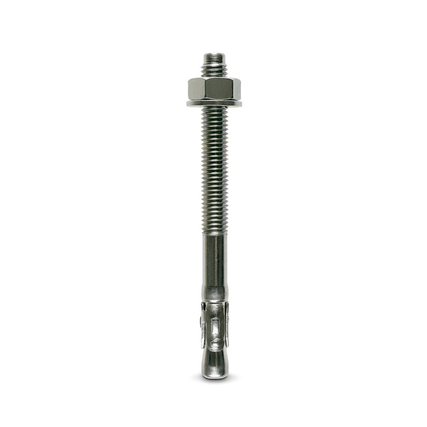
Wedge Anchor Bolt
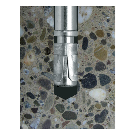
ETA Option 7 Approved troughbolt for simple and economical applications.
Technical Data
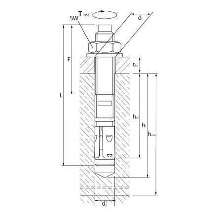
Product Dimensions
| References | Item Code | Tun / DB nr. | NOB nr. | Thread diameter [mm] | Drill Ø x Depth of Drilled Hole [d0 x h1] [mm] | Max. Fixture Thickness [tfix] [mm] | Ø Fixture Hole [df] [mm] | Embedment depth [hef] [mm] | Total Length [L] [mm] | Thread length [f] [mm] | Packaging [pce] |
|---|---|---|---|---|---|---|---|---|---|---|---|
| WA M6-65/10 | WA06065 | - | - | 6 | 6x55 | 10 | 7 | 40 | 65 | 30 | 100 |
| WA M6-85/30 | WA06085 | - | - | 6 | 6x55 | 30 | 7 | 40 | 85 | 40 | 100 |
| WA M8-68/5 | WA08068 | - | - | 8 | 8x65 | 5 | 9 | 45 | 68 | 40 | 50 |
| WA M8-73/10 | WA08073 | - | - | 8 | 8x65 | 10 | 9 | 45 | 73 | 45 | 50 |
| WA M8-83/20 | WA08083 | - | - | 8 | 8x65 | 20 | 9 | 45 | 83 | 45 | 50 |
| WA M8-93/30 | WA08093 | - | - | 8 | 8x65 | 30 | 9 | 45 | 93 | 50 | 50 |
| WA M8-103/40 | WA08103 | - | - | 8 | 8x65 | 40 | 9 | 45 | 103 | 50 | 50 |
| WA M8-113/50 | WA08113 | - | - | 8 | 8x65 | 50 | 9 | 45 | 113 | 60 | 50 |
| WA M8-133/70 | WA08133 | - | - | 8 | 8x65 | 70 | 9 | 45 | 133 | 85 | 50 |
| WA M8-163/100 | WA08163 | - | - | 8 | 8x65 | 100 | 9 | 45 | 163 | 100 | 50 |
| WA M10-78/5 | WA10078 | - | - | 10 | 10x70 | 5 | 12 | 50 | 78 | 40 | 50 |
| WA M10-83/10 | WA10083 | - | - | 10 | 10x70 | 10 | 12 | 50 | 83 | 40 | 50 |
| WA M10-93/20 | WA10093 | - | - | 10 | 10x70 | 20 | 12 | 50 | 93 | 50 | 50 |
| WA M10-103/30 | WA10103 | - | - | 10 | 10x70 | 30 | 12 | 50 | 103 | 50 | 50 |
| WA M10-113/40 | WA10113 | - | - | 10 | 10x70 | 40 | 12 | 50 | 113 | 60 | 50 |
| WA M10-123/50 | WA10123 | - | - | 10 | 10x70 | 50 | 12 | 50 | 123 | 60 | 50 |
| WA M10-143/70 | WA10143 | - | - | 10 | 10x70 | 70 | 12 | 50 | 143 | 70 | 50 |
| WA M10-173/100 | WA10173 | - | - | 10 | 10x70 | 100 | 12 | 50 | 173 | 80 | 50 |
| WA M10-213/140 | WA10213 | - | - | 10 | 10x70 | 140 | 12 | 50 | 213 | 100 | 50 |
| WA M10-233/160 | WA10233 | - | - | 10 | 10x70 | 160 | 12 | 50 | 233 | 125 | 50 |
| WA M12-104/5 | WA12104 | - | - | 12 | 12x90 | 5 | 14 | 65 | 104 | 60 | 25 |
| WA M12-109/10 | WA12109 | - | - | 12 | 12x90 | 10 | 14 | 65 | 109 | 60 | 25 |
| WA M12-119/20 | WA12119 | - | - | 12 | 12x90 | 20 | 14 | 65 | 119 | 70 | 25 |
| WA M12-129/30 | WA12129 | - | - | 12 | 12x90 | 30 | 14 | 65 | 129 | 70 | 25 |
| WA M12-139/40 | WA12139 | - | - | 12 | 12x90 | 40 | 14 | 65 | 139 | 80 | 25 |
| WA M12-149/50 | WA12149 | - | - | 12 | 12x90 | 50 | 14 | 65 | 149 | 100 | 25 |
| WA M12-179/80 | WA12179 | - | - | 12 | 12x90 | 80 | 14 | 65 | 179 | 110 | 25 |
| WA M12-199/100 | WA12199 | - | - | 12 | 12x90 | 100 | 14 | 65 | 199 | 110 | 25 |
| WA M12-219/120 | WA12219 | - | - | 12 | 12x90 | 120 | 14 | 65 | 219 | 125 | 25 |
| WA M12-239/140 | WA12239 | - | - | 12 | 12x90 | 140 | 14 | 65 | 239 | 125 | 25 |
| WA M12-259/160 | WA12259 | - | - | 12 | 12x90 | 160 | 14 | 65 | 259 | 125 | 20 |
| WA M16-110/5 | WA16110 | - | - | 16 | 16x110 | 5 | 18 | 70 | 110 | 50 | 20 |
| WA M16-151/30 | WA16151 | - | - | 16 | 16x110 | 30 | 18 | 80 | 151 | 80 | 20 |
| WA M16-171/50 | WA16171 | - | - | 16 | 16x110 | 50 | 18 | 80 | 171 | 80 | 20 |
| WA M16-201/80 | WA16201 | - | - | 16 | 16x110 | 80 | 18 | 80 | 201 | 100 | 10 |
| WA M16-221/100 | WA16221 | - | - | 16 | 16x110 | 100 | 18 | 80 | 221 | 100 | 10 |
| WA M16-261/140 | WA16261 | - | - | 16 | 16x110 | 140 | 18 | 80 | 261 | 110 | 10 |
| WA M16-281/160 | WA16281 | - | - | 16 | 16x110 | 160 | 18 | 80 | 281 | 125 | 10 |
| WA M16-321/200 | WA16321 | - | - | 16 | 16x110 | 200 | 18 | 80 | 321 | 150 | 10 |
| WA M20-120/5 | WA2012 | - | - | 20 | 20x130 | 5 | 22 | 100 | 120 | 100 | 10 |
| WA M20-173/30* | WA20173 | - | - | 20 | 20x130 | 30 | 22 | 100 | 173 | 100 | 10 |
| WA M20-193/60* | WA20193 | - | - | 20 | 20x130 | 60 | 22 | 100 | 193 | 100 | 10 |
| WA M20-223/80* | WA20223 | - | - | 20 | 20x130 | 80 | 22 | 100 | 223 | 125 | 10 |
| WA M20-263/120* | WA20263 | - | - | 20 | 20x130 | 120 | 22 | 100 | 263 | 150 | 10 |
* Not included in the approval
Recommended loads / for single anchors / with no edge distances or spacings
| References | Non-cracked concrete | Non-cracked concrete | Bending moment (1-6) [Nm] | ||||||||
|---|---|---|---|---|---|---|---|---|---|---|---|
| Tension (1-2) [kN] | Shear (1-3) [kN] | Tension - NR,d | Shear - VR,d | ||||||||
| C20/25 | C30/37 | C40/50 | C50/60 | C20/25 | C30/37 | C40/50 | C50/60 | C20/25 [kN] | C20/25 [kN] | ||
| WA M6-65/10 | 4.3 | 4.6 | 5 | 5.3 | 3.4 | 3.4 | 3.4 | 3.4 | - | - | 5.7 |
| WA M6-85/30 | 4.3 | 4.6 | 5 | 5.3 | 3.4 | 3.4 | 3.4 | 3.4 | - | - | 5.7 |
| WA M8-68/5 | 5.7 | 7 | 8.1 | 8.9 | 5.4 | 5.4 | 5.4 | 5.4 | - | - | 13.8 |
| WA M8-73/10 | 5.7 | 7 | 8.1 | 8.9 | 5.4 | 5.4 | 5.4 | 5.4 | - | - | 13.8 |
| WA M8-83/20 | 5.7 | 7 | 8.1 | 8.9 | 5.4 | 5.4 | 5.4 | 5.4 | - | - | 13.8 |
| WA M8-93/30 | 5.7 | 7 | 8.1 | 8.9 | 5.4 | 5.4 | 5.4 | 5.4 | - | - | 13.8 |
| WA M8-103/40 | 5.7 | 7 | 8.1 | 8.9 | 5.4 | 5.4 | 5.4 | 5.4 | - | - | 13.8 |
| WA M8-113/50 | 5.7 | 7 | 8.1 | 8.9 | 5.4 | 5.4 | 5.4 | 5.4 | - | - | 13.8 |
| WA M8-133/70 | 5.7 | 7 | 8.1 | 8.9 | 5.4 | 5.4 | 5.4 | 5.4 | - | - | 13.8 |
| WA M8-163/100 | 5.7 | 7 | 8.1 | 8.9 | 5.4 | 5.4 | 5.4 | 5.4 | - | - | 13.8 |
| WA M10-78/5 | 7.6 | 9.3 | 10.7 | 11.8 | 8.8 | 9.7 | 9.7 | 9.7 | - | - | 27.1 |
| WA M10-83/10 | 7.6 | 9.3 | 10.7 | 11.8 | 8.8 | 9.7 | 9.7 | 9.7 | - | - | 27.1 |
| WA M10-93/20 | 7.6 | 9.3 | 10.7 | 11.8 | 8.8 | 9.7 | 9.7 | 9.7 | - | - | 27.1 |
| WA M10-103/30 | 7.6 | 9.3 | 10.7 | 11.8 | 8.8 | 9.7 | 9.7 | 9.7 | - | - | 27.1 |
| WA M10-113/40 | 7.6 | 9.3 | 10.7 | 11.8 | 8.8 | 9.7 | 9.7 | 9.7 | - | - | 27.1 |
| WA M10-123/50 | 7.6 | 9.3 | 10.7 | 11.8 | 8.8 | 9.7 | 9.7 | 9.7 | - | - | 27.1 |
| WA M10-143/70 | 7.6 | 9.3 | 10.7 | 11.8 | 8.8 | 9.7 | 9.7 | 9.7 | - | - | 27.1 |
| WA M10-173/100 | 7.6 | 9.3 | 10.7 | 11.8 | 8.8 | 9.7 | 9.7 | 9.7 | - | - | 27.1 |
| WA M10-213/140 | 7.6 | 9.3 | 10.7 | 11.8 | 8.8 | 9.7 | 9.7 | 9.7 | - | - | 27.1 |
| WA M10-233/160 | 7.6 | 9.3 | 10.7 | 11.8 | 8.8 | 9.7 | 9.7 | 9.7 | - | - | 27.1 |
| WA M12-104/5 | 12.6 | 15.4 | 17.8 | 19.5 | 14.3 | 14.3 | 14.3 | 14.3 | - | - | 47.1 |
| WA M12-109/10 | 12.6 | 15.4 | 17.8 | 19.5 | 14.3 | 14.3 | 14.3 | 14.3 | - | - | 47.1 |
| WA M12-119/20 | 12.6 | 15.4 | 17.8 | 19.5 | 14.3 | 14.3 | 14.3 | 14.3 | - | - | 47.1 |
| WA M12-129/30 | 12.6 | 15.4 | 17.8 | 19.5 | 14.3 | 14.3 | 14.3 | 14.3 | - | - | 47.1 |
| WA M12-139/40 | 12.6 | 15.4 | 17.8 | 19.5 | 14.3 | 14.3 | 14.3 | 14.3 | - | - | 47.1 |
| WA M12-149/50 | 12.6 | 15.4 | 17.8 | 19.5 | 14.3 | 14.3 | 14.3 | 14.3 | - | - | 47.1 |
| WA M12-179/80 | 12.6 | 15.4 | 17.8 | 19.5 | 14.3 | 14.3 | 14.3 | 14.3 | - | - | 47.1 |
| WA M12-199/100 | 12.6 | 15.4 | 17.8 | 19.5 | 14.3 | 14.3 | 14.3 | 14.3 | - | - | 47.1 |
| WA M12-219/120 | 12.6 | 15.4 | 17.8 | 19.5 | 14.3 | 14.3 | 14.3 | 14.3 | - | - | 47.1 |
| WA M12-239/140 | 12.6 | 15.4 | 17.8 | 19.5 | 14.3 | 14.3 | 14.3 | 14.3 | - | - | 47.1 |
| WA M12-259/160 | 12.6 | 15.4 | 17.8 | 19.5 | 14.3 | 14.3 | 14.3 | 14.3 | - | - | 47.1 |
| WA M16-110/5 | 17.2 | 21 | 24.3 | 26.7 | 26.9 | 26.9 | 26.9 | 26.9 | - | - | 111 |
| WA M16-151/30 | 17.2 | 21 | 24.3 | 26.7 | 26.9 | 26.9 | 26.9 | 26.9 | - | - | 111 |
| WA M16-171/50 | 17.2 | 21 | 24.3 | 26.7 | 26.9 | 26.9 | 26.9 | 26.9 | - | - | 111 |
| WA M16-201/80 | 17.2 | 21 | 24.3 | 26.7 | 26.9 | 26.9 | 26.9 | 26.9 | - | - | 111 |
| WA M16-221/100 | 17.2 | 21 | 24.3 | 26.7 | 26.9 | 26.9 | 26.9 | 26.9 | - | - | 111 |
| WA M16-261/140 | 17.2 | 21 | 24.3 | 26.7 | 26.9 | 26.9 | 26.9 | 26.9 | - | - | 111 |
| WA M16-281/160 | 17.2 | 21 | 24.3 | 26.7 | 26.9 | 26.9 | 26.9 | 26.9 | - | - | 111 |
| WA M16-321/200 | 17.2 | 21 | 24.3 | 26.7 | 26.9 | 26.9 | 26.9 | 26.9 | - | - | 111 |
| WA M20-120/5 | - | - | - | - | - | - | - | - | - | - | - |
| WA M20-173/30* | 19.9 | 19.9 | 19.9 | 19.9 | 26.7 | 26.7 | 26.7 | 26.7 | - | - | 141.4 |
| WA M20-193/60* | 19.9 | 19.9 | 19.9 | 19.9 | 26.7 | 26.7 | 26.7 | 26.7 | - | - | 141.4 |
| WA M20-223/80* | 19.9 | 19.9 | 19.9 | 19.9 | 26.7 | 26.7 | 26.7 | 26.7 | - | - | 141.4 |
| WA M20-263/120* | 19.9 | 19.9 | 19.9 | 19.9 | 26.7 | 26.7 | 26.7 | 26.7 | - | - | 141.4 |
* Not included in the approval
1. The recommended loads have been calculated using the partial safety factors for resistances stated in ETA-approval(s) and with a partial safety factor for actions of γF=1.4. The loading figures
are valid for unreinforced concrete and reinforced concrete with a rebar spacing s ≥ 15 cm (any diameter) or with a rebar spacing s ≥ 10 cm, if the rebar diameter is 10 mm or smaller.
2. The figures for shear are based on a single anchor without influence of concrete edges. For anchorages close to edges (c ≤ max [10 hef; 60d]) the concrete edge failure shall be checked per
ETAG 001, Annex C, design method A.
3. Concrete is considered non-cracked when the tensile stress within the concrete is L equals the tensile
stress within the concrete induced by external loads, anchors loads included).
Design capacities - single anchor - no edge distances
| References | Design capacity - Non-cracked concrete (3) | ||||||||
|---|---|---|---|---|---|---|---|---|---|
| Tension - NRd (1) [kN] | Shear - VRd (1-2) [kN] | Bending moment MRd [Nm] | |||||||
| C20/25 | C30/37 | C40/50 | C50/60 | C20/25 | C30/37 | C40/50 | C50/60 | ||
| WA M6-65/10 | 6 | 6.5 | 7 | 7.4 | 4.8 | 4.8 | 4.8 | 4.8 | 8 |
| WA M6-85/30 | 6 | 6.5 | 7 | 7.4 | 4.8 | 4.8 | 4.8 | 4.8 | 8 |
| WA M8-68/5 | 8 | 9.8 | 11.3 | 12.4 | 7.6 | 7.6 | 7.6 | 7.6 | 19.3 |
| WA M8-73/10 | 8 | 9.8 | 11.3 | 12.4 | 7.6 | 7.6 | 7.6 | 7.6 | 19.3 |
| WA M8-83/20 | 8 | 9.8 | 11.3 | 12.4 | 7.6 | 7.6 | 7.6 | 7.6 | 19.3 |
| WA M8-93/30 | 8 | 9.8 | 11.3 | 12.4 | 7.6 | 7.6 | 7.6 | 7.6 | 19.3 |
| WA M8-103/40 | 8 | 9.8 | 11.3 | 12.4 | 7.6 | 7.6 | 7.6 | 7.6 | 19.3 |
| WA M8-113/50 | 8 | 9.8 | 11.3 | 12.4 | 7.6 | 7.6 | 7.6 | 7.6 | 19.3 |
| WA M8-133/70 | 8 | 9.8 | 11.3 | 12.4 | 7.6 | 7.6 | 7.6 | 7.6 | 19.3 |
| WA M8-163/100 | 8 | 9.8 | 11.3 | 12.4 | 7.6 | 7.6 | 7.6 | 7.6 | 19.3 |
| WA M10-78/5 | 10.7 | 13 | 15 | 16.5 | 11.9 | 13.6 | 13.6 | 13.6 | 38 |
| WA M10-83/10 | 10.7 | 13 | 15 | 16.5 | 11.9 | 13.6 | 13.6 | 13.6 | 38 |
| WA M10-93/20 | 10.7 | 13 | 15 | 16.5 | 11.9 | 13.6 | 13.6 | 13.6 | 38 |
| WA M10-103/30 | 10.7 | 13 | 15 | 16.5 | 11.9 | 13.6 | 13.6 | 13.6 | 38 |
| WA M10-113/40 | 10.7 | 13 | 15 | 16.5 | 11.9 | 13.6 | 13.6 | 13.6 | 38 |
| WA M10-123/50 | 10.7 | 13 | 15 | 16.5 | 11.9 | 13.6 | 13.6 | 13.6 | 38 |
| WA M10-143/70 | 10.7 | 13 | 15 | 16.5 | 11.9 | 13.6 | 13.6 | 13.6 | 38 |
| WA M10-173/100 | 10.7 | 13 | 15 | 16.5 | 11.9 | 13.6 | 13.6 | 13.6 | 38 |
| WA M10-213/140 | 10.7 | 13 | 15 | 16.5 | 11.9 | 13.6 | 13.6 | 13.6 | 38 |
| WA M10-233/160 | 10.7 | 13 | 15 | 16.5 | 11.9 | 13.6 | 13.6 | 13.6 | 38 |
| WA M12-104/5 | 17.6 | 21.5 | 24.9 | 27.3 | 20 | 20 | 20 | 20 | 66 |
| WA M12-109/10 | 17.6 | 21.5 | 24.9 | 27.3 | 20 | 20 | 20 | 20 | 66 |
| WA M12-119/20 | 17.6 | 21.5 | 24.9 | 27.3 | 20 | 20 | 20 | 20 | 66 |
| WA M12-129/30 | 17.6 | 21.5 | 24.9 | 27.3 | 20 | 20 | 20 | 20 | 66 |
| WA M12-139/40 | 17.6 | 21.5 | 24.9 | 27.3 | 20 | 20 | 20 | 20 | 66 |
| WA M12-149/50 | 17.6 | 21.5 | 24.9 | 27.3 | 20 | 20 | 20 | 20 | 66 |
| WA M12-179/80 | 17.6 | 21.5 | 24.9 | 27.3 | 20 | 20 | 20 | 20 | 66 |
| WA M12-199/100 | 17.6 | 21.5 | 24.9 | 27.3 | 20 | 20 | 20 | 20 | 66 |
| WA M12-219/120 | 17.6 | 21.5 | 24.9 | 27.3 | 20 | 20 | 20 | 20 | 66 |
| WA M12-239/140 | 17.6 | 21.5 | 24.9 | 27.3 | 20 | 20 | 20 | 20 | 66 |
| WA M12-259/160 | 17.6 | 21.5 | 24.9 | 27.3 | 20 | 20 | 20 | 20 | 66 |
| WA M16-110/5 | 24.1 | 29.4 | 34 | 37.3 | 37.6 | 37.6 | 37.6 | 37.6 | 155.3 |
| WA M16-151/30 | 24.1 | 29.4 | 34 | 37.3 | 37.6 | 37.6 | 37.6 | 37.6 | 155.3 |
| WA M16-171/50 | 24.1 | 29.4 | 34 | 37.3 | 37.6 | 37.6 | 37.6 | 37.6 | 155.3 |
| WA M16-201/80 | 24.1 | 29.4 | 34 | 37.3 | 37.6 | 37.6 | 37.6 | 37.6 | 155.3 |
| WA M16-221/100 | 24.1 | 29.4 | 34 | 37.3 | 37.6 | 37.6 | 37.6 | 37.6 | 155.3 |
| WA M16-261/140 | 24.1 | 29.4 | 34 | 37.3 | 37.6 | 37.6 | 37.6 | 37.6 | 155.3 |
| WA M16-281/160 | 24.1 | 29.4 | 34 | 37.3 | 37.6 | 37.6 | 37.6 | 37.6 | 155.3 |
| WA M16-321/200 | 24.1 | 29.4 | 34 | 37.3 | 37.6 | 37.6 | 37.6 | 37.6 | 155.3 |
| WA M20-120/5 | 27.9 | 27.9 | 27.9 | 27.9 | 37.4 | 37.4 | 37.4 | 37.4 | 198 |
| WA M20-173/30* | 27.9 | 27.9 | 27.9 | 27.9 | 37.4 | 37.4 | 37.4 | 37.4 | 198 |
| WA M20-193/60* | 27.9 | 27.9 | 27.9 | 27.9 | 37.4 | 37.4 | 37.4 | 37.4 | 198 |
| WA M20-223/80* | 27.9 | 27.9 | 27.9 | 27.9 | 37.4 | 37.4 | 37.4 | 37.4 | 198 |
| WA M20-263/120* | 27.9 | 27.9 | 27.9 | 27.9 | 37.4 | 37.4 | 37.4 | 37.4 | 198 |
1. The design loads loads have been calculated using the partial safety factors for resistances stated in ETA-approval(s). The loading figures are valid for unreinforced concrete and reinforced concrete with a rebar spacing s ≥ 15 cm (any diameter) or with a rebar spacing s ≥ 10 cm, if the rebar diameter is 10mm or smaller.
2. The figures for shear are based on a single anchor without influence of concrete edges. For anchorages close to edges (c ≤ max [10 hef; 60d]) the concrete edge failure shall be checked per ETAG 001, Annex C, design method A.
3. Concrete is considered non-cracked when the tensile stress within the concrete is\sigmaL +\sigmaR ≤ 0. In the absence of detailed verification\sigmaR = 3 N/mm² can be assumed (\sigmaL equals the tensile stress within the concrete induced by external loads, anchors loads included).
*Not covered by ETA-11/0080
Recommended capacities - single anchor - no edge distances
| References | Recommended capacity - Non-cracked concrete | ||||||||
|---|---|---|---|---|---|---|---|---|---|
| Tension - Nrec(1-2) [kN] | Shear - Vrec(1-3) [kN] | Bending moment Mrec (1-6) [Nm] | |||||||
| C20/25 | C30/37 | C40/50 | C50/60 | C20/25 | C30/37 | C40/50 | C50/60 | ||
| WA M6-65/10 | 4.3 | 4.6 | 5 | 5.3 | 3.4 | 3.4 | 3.4 | 3.4 | 5.7 |
| WA M6-85/30 | 4.3 | 4.6 | 5 | 5.3 | 3.4 | 3.4 | 3.4 | 3.4 | 5.7 |
| WA M8-68/5 | 5.7 | 7 | 8.1 | 8.9 | 5.4 | 5.4 | 5.4 | 5.4 | 13.8 |
| WA M8-73/10 | 5.7 | 7 | 8.1 | 8.9 | 5.4 | 5.4 | 5.4 | 5.4 | 13.8 |
| WA M8-83/20 | 5.7 | 7 | 8.1 | 8.9 | 5.4 | 5.4 | 5.4 | 5.4 | 13.8 |
| WA M8-93/30 | 5.7 | 7 | 8.1 | 8.9 | 5.4 | 5.4 | 5.4 | 5.4 | 13.8 |
| WA M8-103/40 | 5.7 | 7 | 8.1 | 8.9 | 5.4 | 5.4 | 5.4 | 5.4 | 13.8 |
| WA M8-113/50 | 5.7 | 7 | 8.1 | 8.9 | 5.4 | 5.4 | 5.4 | 5.4 | 13.8 |
| WA M8-133/70 | 5.7 | 7 | 8.1 | 8.9 | 5.4 | 5.4 | 5.4 | 5.4 | 13.8 |
| WA M8-163/100 | 5.7 | 7 | 8.1 | 8.9 | 5.4 | 5.4 | 5.4 | 5.4 | 13.8 |
| WA M10-78/5 | 7.6 | 9.3 | 10.7 | 11.8 | 8.8 | 9.7 | 9.7 | 9.7 | 27.1 |
| WA M10-83/10 | 7.6 | 9.3 | 10.7 | 11.8 | 8.8 | 9.7 | 9.7 | 9.7 | 27.1 |
| WA M10-93/20 | 7.6 | 9.3 | 10.7 | 11.8 | 8.8 | 9.7 | 9.7 | 9.7 | 27.1 |
| WA M10-103/30 | 7.6 | 9.3 | 10.7 | 11.8 | 8.8 | 9.7 | 9.7 | 9.7 | 27.1 |
| WA M10-113/40 | 7.6 | 9.3 | 10.7 | 11.8 | 8.8 | 9.7 | 9.7 | 9.7 | 27.1 |
| WA M10-123/50 | 7.6 | 9.3 | 10.7 | 11.8 | 8.8 | 9.7 | 9.7 | 9.7 | 27.1 |
| WA M10-143/70 | 7.6 | 9.3 | 10.7 | 11.8 | 8.8 | 9.7 | 9.7 | 9.7 | 27.1 |
| WA M10-173/100 | 7.6 | 9.3 | 10.7 | 11.8 | 8.8 | 9.7 | 9.7 | 9.7 | 27.1 |
| WA M10-213/140 | 7.6 | 9.3 | 10.7 | 11.8 | 8.8 | 9.7 | 9.7 | 9.7 | 27.1 |
| WA M10-233/160 | 7.6 | 9.3 | 10.7 | 11.8 | 8.8 | 9.7 | 9.7 | 9.7 | 27.1 |
| WA M12-104/5 | 12.6 | 15.4 | 17.8 | 19.5 | 14.3 | 14.3 | 14.3 | 14.3 | 47.1 |
| WA M12-109/10 | 12.6 | 15.4 | 17.8 | 19.5 | 14.3 | 14.3 | 14.3 | 14.3 | 47.1 |
| WA M12-119/20 | 12.6 | 15.4 | 17.8 | 19.5 | 14.3 | 14.3 | 14.3 | 14.3 | 47.1 |
| WA M12-129/30 | 12.6 | 15.4 | 17.8 | 19.5 | 14.3 | 14.3 | 14.3 | 14.3 | 47.1 |
| WA M12-139/40 | 12.6 | 15.4 | 17.8 | 19.5 | 14.3 | 14.3 | 14.3 | 14.3 | 47.1 |
| WA M12-149/50 | 12.6 | 15.4 | 17.8 | 19.5 | 14.3 | 14.3 | 14.3 | 14.3 | 47.1 |
| WA M12-179/80 | 12.6 | 15.4 | 17.8 | 19.5 | 14.3 | 14.3 | 14.3 | 14.3 | 47.1 |
| WA M12-199/100 | 12.6 | 15.4 | 17.8 | 19.5 | 14.3 | 14.3 | 14.3 | 14.3 | 47.1 |
| WA M12-219/120 | 12.6 | 15.4 | 17.8 | 19.5 | 14.3 | 14.3 | 14.3 | 14.3 | 47.1 |
| WA M12-239/140 | 12.6 | 15.4 | 17.8 | 19.5 | 14.3 | 14.3 | 14.3 | 14.3 | 47.1 |
| WA M12-259/160 | 12.6 | 15.4 | 17.8 | 19.5 | 14.3 | 14.3 | 14.3 | 14.3 | 47.1 |
| WA M16-110/5 | 17.2 | 21 | 24.3 | 26.7 | 26.9 | 26.9 | 26.9 | 26.9 | 111 |
| WA M16-151/30 | 17.2 | 21 | 24.3 | 26.7 | 26.9 | 26.9 | 26.9 | 26.9 | 111 |
| WA M16-171/50 | 17.2 | 21 | 24.3 | 26.7 | 26.9 | 26.9 | 26.9 | 26.9 | 111 |
| WA M16-201/80 | 17.2 | 21 | 24.3 | 26.7 | 26.9 | 26.9 | 26.9 | 26.9 | 111 |
| WA M16-221/100 | 17.2 | 21 | 24.3 | 26.7 | 26.9 | 26.9 | 26.9 | 26.9 | 111 |
| WA M16-261/140 | 17.2 | 21 | 24.3 | 26.7 | 26.9 | 26.9 | 26.9 | 26.9 | 111 |
| WA M16-281/160 | 17.2 | 21 | 24.3 | 26.7 | 26.9 | 26.9 | 26.9 | 26.9 | 111 |
| WA M16-321/200 | 17.2 | 21 | 24.3 | 26.7 | 26.9 | 26.9 | 26.9 | 26.9 | 111 |
| WA M20-120/5 | 19.9 | 19.9 | 19.9 | 19.9 | 26.7 | 26.7 | 26.7 | 26.7 | - |
| WA M20-173/30* | 19.9 | 19.9 | 19.9 | 19.9 | 26.7 | 26.7 | 26.7 | 26.7 | 141.4 |
| WA M20-193/60* | 19.9 | 19.9 | 19.9 | 19.9 | 26.7 | 26.7 | 26.7 | 26.7 | 141.4 |
| WA M20-223/80* | 19.9 | 19.9 | 19.9 | 19.9 | 26.7 | 26.7 | 26.7 | 26.7 | 141.4 |
| WA M20-263/120* | 19.9 | 19.9 | 19.9 | 19.9 | 26.7 | 26.7 | 26.7 | 26.7 | 141.4 |
1. The recommended loads have been calculated using the partial safety factors for resistances stated in ETA-approval(s) and with a partial safety factor for actions of γF=1.4. The loading figures
are valid for unreinforced concrete and reinforced concrete with a rebar spacing s ≥ 15 cm (any diameter) or with a rebar spacing s ≥ 10 cm, if the rebar diameter is 10 mm or smaller.
2. The figures for shear are based on a single anchor without influence of concrete edges. For anchorages close to edges (c ≤ max [10 hef; 60d]) the concrete edge failure shall be checked per
ETAG 001, Annex C, design method A.
3. Concrete is considered non-cracked when the tensile stress within the concrete is\sigmaL +\sigmaR ≤ 0. In the absence of detailed verification\sigmaR = 3 N/mm² can be assumed (\sigmaL equals the tensile stress within the concrete induced by external loads, anchors loads included).
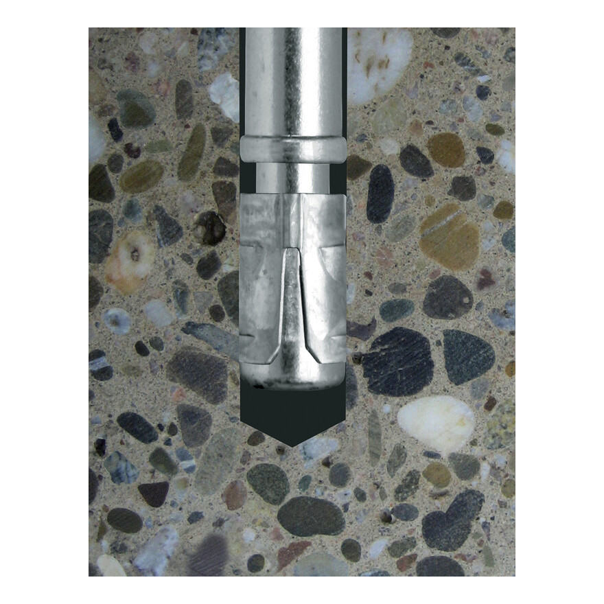
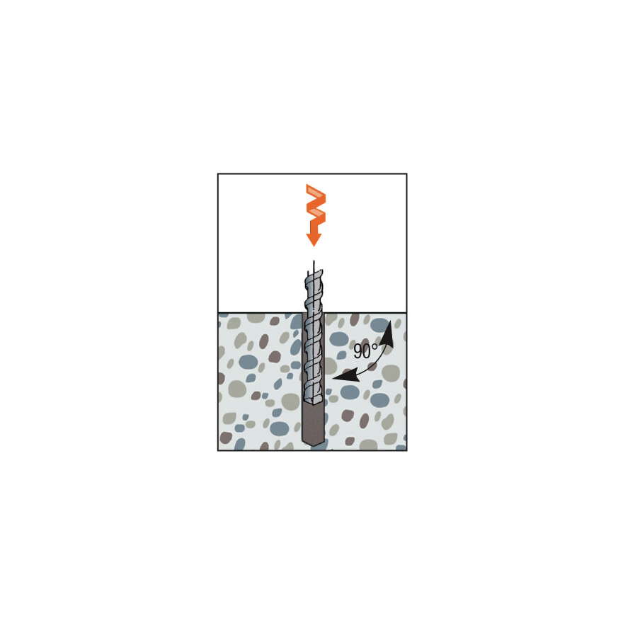
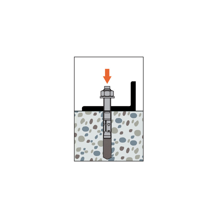
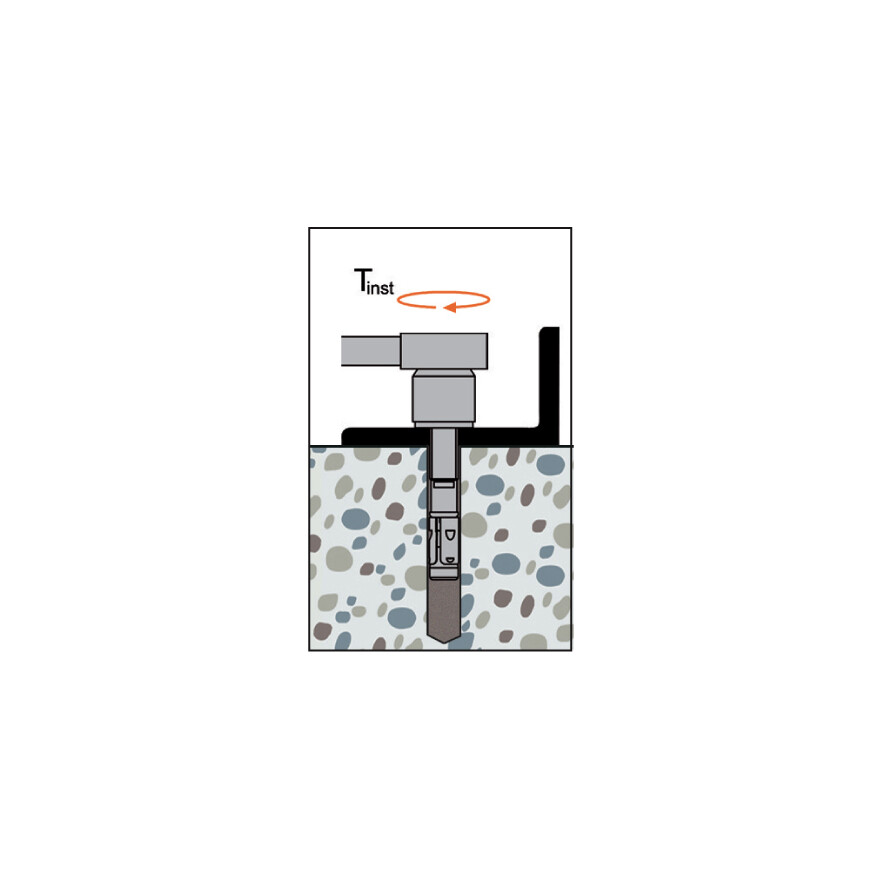
Installation
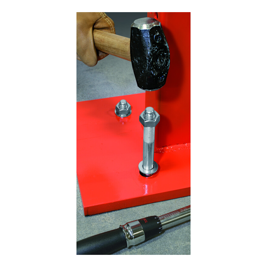
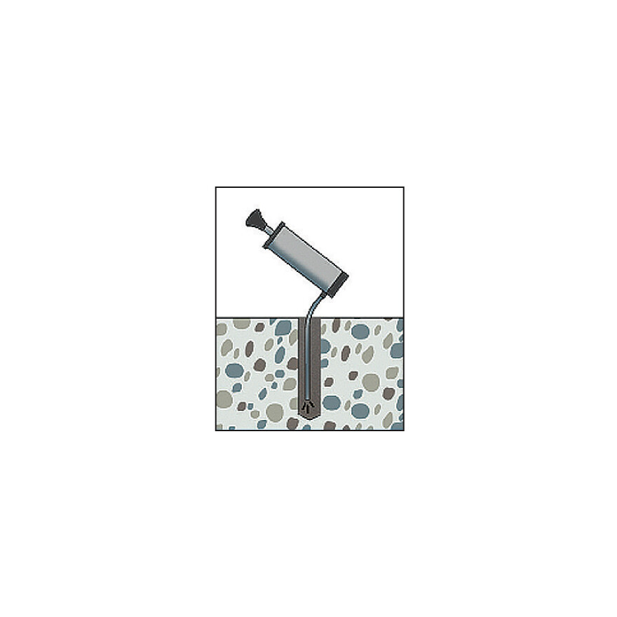
Installation
Installation
.-
Spacing, Edge Distance and Member Thickness
| References | Ø drilling hole [d0] [mm] | Min. drill depth [h1] [mm] | &Oslmash drilling fixture [df] [mm] | Wrench size [SW] [mm] | Installation torque [Tinst] [Nm] | Embedment depth [hef] [mm] | Min. support thickness [hmin] [mm] | Characteristic spacing(5) - Scr,N [scr,N] [mm] | Characteristic edge distance [ccr,N] [mm] |
|---|---|---|---|---|---|---|---|---|---|
| WA M6-65/10 | 6 | 55 | 7 | 10 | 8 | 40 | 100 | 120 | 60 |
| WA M6-85/30 | 6 | 55 | 7 | 10 | 8 | 40 | 100 | 120 | 60 |
| WA M8-68/5 | 8 | 65 | 9 | 13 | 15 | 45 | 100 | 135 | 68 |
| WA M8-73/10 | 8 | 65 | 9 | 13 | 15 | 45 | 100 | 135 | 68 |
| WA M8-83/20 | 8 | 65 | 9 | 13 | 15 | 45 | 100 | 135 | 68 |
| WA M8-93/30 | 8 | 65 | 9 | 13 | 15 | 45 | 100 | 135 | 68 |
| WA M8-103/40 | 8 | 65 | 9 | 13 | 15 | 45 | 100 | 135 | 68 |
| WA M8-113/50 | 8 | 65 | 9 | 13 | 15 | 45 | 100 | 135 | 68 |
| WA M8-133/70 | 8 | 65 | 9 | 13 | 15 | 45 | 100 | 135 | 68 |
| WA M8-163/100 | 8 | 65 | 9 | 13 | 15 | 45 | 100 | 135 | 68 |
| WA M10-78/5 | 10 | 70 | 12 | 17 | 30 | 50 | 100 | 150 | 75 |
| WA M10-83/10 | 10 | 70 | 12 | 17 | 30 | 50 | 100 | 150 | 75 |
| WA M10-93/20 | 10 | 70 | 12 | 17 | 30 | 50 | 100 | 150 | 75 |
| WA M10-103/30 | 10 | 70 | 12 | 17 | 30 | 50 | 100 | 150 | 75 |
| WA M10-113/40 | 10 | 70 | 12 | 17 | 30 | 50 | 100 | 150 | 75 |
| WA M10-123/50 | 10 | 70 | 12 | 17 | 30 | 50 | 100 | 150 | 75 |
| WA M10-143/70 | 10 | 70 | 12 | 17 | 30 | 50 | 100 | 150 | 75 |
| WA M10-173/100 | 10 | 70 | 12 | 17 | 30 | 50 | 100 | 150 | 75 |
| WA M10-213/140 | 10 | 70 | 12 | 17 | 30 | 50 | 100 | 150 | 75 |
| WA M10-233/160 | 10 | 70 | 12 | 17 | 30 | 50 | 100 | 150 | 75 |
| WA M12-104/5 | 12 | 90 | 14 | 19 | 50 | 65 | 130 | 195 | 98 |
| WA M12-109/10 | 12 | 90 | 14 | 19 | 50 | 65 | 130 | 195 | 98 |
| WA M12-119/20 | 12 | 90 | 14 | 19 | 50 | 65 | 130 | 195 | 98 |
| WA M12-129/30 | 12 | 90 | 14 | 19 | 50 | 65 | 130 | 195 | 98 |
| WA M12-139/40 | 12 | 90 | 14 | 19 | 50 | 65 | 130 | 195 | 98 |
| WA M12-149/50 | 12 | 90 | 14 | 19 | 50 | 65 | 130 | 195 | 98 |
| WA M12-179/80 | 12 | 90 | 14 | 19 | 50 | 65 | 130 | 195 | 98 |
| WA M12-199/100 | 12 | 90 | 14 | 19 | 50 | 65 | 130 | 195 | 98 |
| WA M12-219/120 | 12 | 90 | 14 | 19 | 50 | 65 | 130 | 195 | 98 |
| WA M12-239/140 | 12 | 90 | 14 | 19 | 50 | 65 | 130 | 195 | 98 |
| WA M12-259/160 | 12 | 90 | 14 | 19 | 50 | 65 | 130 | 195 | 98 |
| WA M16-110/5 | 16 | 110 | 18 | 24 | 100 | 80 | 160 | 240 | 120 |
| WA M16-151/30 | 16 | 110 | 18 | 24 | 100 | 80 | 160 | 240 | 120 |
| WA M16-171/50 | 16 | 110 | 18 | 24 | 100 | 80 | 160 | 240 | 120 |
| WA M16-201/80 | 16 | 110 | 18 | 24 | 100 | 80 | 160 | 240 | 120 |
| WA M16-221/100 | 16 | 110 | 18 | 24 | 100 | 80 | 160 | 240 | 120 |
| WA M16-261/140 | 16 | 110 | 18 | 24 | 100 | 80 | 160 | 240 | 120 |
| WA M16-281/160 | 16 | 110 | 18 | 24 | 100 | 80 | 160 | 240 | 120 |
| WA M16-321/200 | 16 | 110 | 18 | 24 | 100 | 80 | 160 | 240 | 120 |
| WA M20-120/5 | 20 | 130 | 22 | 30 | 200 | 100 | 200 | 300 | 150 |
| WA M20-173/30* | 20 | 130 | 22 | 30 | 200 | 100 | 200 | 300 | 150 |
| WA M20-193/60* | 20 | 130 | 22 | 30 | 200 | 100 | 200 | 300 | 150 |
| WA M20-223/80* | 20 | 130 | 22 | 30 | 200 | 100 | 200 | 300 | 150 |
| WA M20-263/120* | 20 | 130 | 22 | 30 | 200 | 100 | 200 | 300 | 150 |
* Not included in the approval
Installation data
| References | Min. edge distance [cmin] [mm] | Minimum spacing [smin] [mm] | Characteristic spacing(5) - Scr,N [scr,N] [mm] | Characteristic edge distance [ccr,N] [mm] |
|---|---|---|---|---|
| WA M6-65/10 | 40 | 30 | 120 | 60 |
| WA M6-85/30 | 40 | 30 | 120 | 60 |
| WA M8-68/5 | 40 | 40 | 135 | 68 |
| WA M8-73/10 | 40 | 40 | 135 | 68 |
| WA M8-83/20 | 40 | 40 | 135 | 68 |
| WA M8-93/30 | 40 | 40 | 135 | 68 |
| WA M8-103/40 | 40 | 40 | 135 | 68 |
| WA M8-113/50 | 40 | 40 | 135 | 68 |
| WA M8-133/70 | 40 | 40 | 135 | 68 |
| WA M8-163/100 | 40 | 40 | 135 | 68 |
| WA M10-78/5 | 50 | 50 | 150 | 75 |
| WA M10-83/10 | 50 | 50 | 150 | 75 |
| WA M10-93/20 | 50 | 50 | 150 | 75 |
| WA M10-103/30 | 50 | 50 | 150 | 75 |
| WA M10-113/40 | 50 | 50 | 150 | 75 |
| WA M10-123/50 | 50 | 50 | 150 | 75 |
| WA M10-143/70 | 50 | 50 | 150 | 75 |
| WA M10-173/100 | 50 | 50 | 150 | 75 |
| WA M10-213/140 | 50 | 50 | 150 | 75 |
| WA M10-233/160 | 50 | 50 | 150 | 75 |
| WA M12-104/5 | 70 | 70 | 195 | 98 |
| WA M12-109/10 | 70 | 70 | 195 | 98 |
| WA M12-119/20 | 70 | 70 | 195 | 98 |
| WA M12-129/30 | 70 | 70 | 195 | 98 |
| WA M12-139/40 | 70 | 70 | 195 | 98 |
| WA M12-149/50 | 70 | 70 | 195 | 98 |
| WA M12-179/80 | 70 | 70 | 195 | 98 |
| WA M12-199/100 | 70 | 70 | 195 | 98 |
| WA M12-219/120 | 70 | 70 | 195 | 98 |
| WA M12-239/140 | 70 | 70 | 195 | 98 |
| WA M12-259/160 | 70 | 70 | 195 | 98 |
| WA M16-110/5 | 90 | 90 | 240 | 120 |
| WA M16-151/30 | 90 | 90 | 240 | 120 |
| WA M16-171/50 | 90 | 90 | 240 | 120 |
| WA M16-201/80 | 90 | 90 | 240 | 120 |
| WA M16-221/100 | 90 | 90 | 240 | 120 |
| WA M16-261/140 | 90 | 90 | 240 | 120 |
| WA M16-281/160 | 90 | 90 | 240 | 120 |
| WA M16-321/200 | 90 | 90 | 240 | 120 |
| WA M20-120/5 | 120 | 120 | 300 | 150 |
| WA M20-173/30* | 120 | 120 | 300 | 150 |
| WA M20-193/60* | 120 | 120 | 300 | 150 |
| WA M20-223/80* | 120 | 120 | 300 | 150 |
| WA M20-263/120* | 120 | 120 | 300 | 150 |
