LSSU

Light Slope & Skew Adjustable Hangers

With these site adjustable hangers, you can always have the right hanger
available for those special rush projects. This versatile range of products
attaches joists/rafters to timber supports at any slope, up or down or at any
skew, left or right up to and including 45°.

All models are slope and skew adjustable on site, excluding the LSU228/108, LSU228/120 and the LSU124/38 which are slope only.
CE Marking
ETA
Service class 2
Electrogalvanized steel 20 µm

Product Details

Images

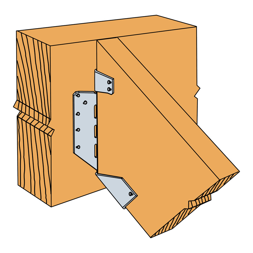
Sloped connection.
LSSU Installation
LSSU Installation

Features

Material

  • Galvanized steel S250GD + Z275 according to NF EN 10346 or G90 according to ASTM A653.
  • Thickness: LSSU - 1.2mm - 1.5mm - 1.6mm / LSU - 2mm.

Application

Suitable On

  • Supporting member: solid wood, composite lumber, glued-laminated wood, etc.
  • Supported member: I-beams, solid wood, composites, etc.

When to Use

  • Fastening of rafters
  • Principal rafters
  • Headers, etc.

Technical Data

Product Dimensions

References Product Dimensions [mm]
A B C D t
LSSU216/454521690441.2
LSSU170/505017090581.2
LSSU216/606021690501.2
LSSU216/909021690691.5
LSSU170/10010017090801.2

* Bending in slope only
SCL: Structural Composite Lumber

Product capacities - Timber to timber -sloped only

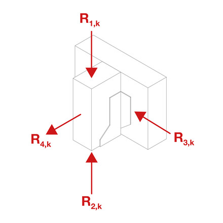
References Characteristic Capacities [kN]
R1.k R2.k
I-joist LVL flanges Solid Sawn Flanged I-joist or C24 Solid Section I-joist LVL flanges Solid Sawn Flanged I-joist or C24 Solid Section
LSSU216/455.19.92.44
LSSU170/50-11.4-5.7
LSSU216/609.19.92.44
LSSU216/9011.112.53.02.3
LSSU170/100-13.1-5.7

Product capacities - Timber to timber - skewed or sloped & skewed

References Characteristic Capacities [kN]
R1.k R2.k
I-joist LVL Flanges Solid Sawn Flanged I-joist or C24 Solid section Solid Section - Timber C24 I-joist LVL Flanges Solid Sawn Flanged I-joist or C24 Solid section Solid Section - Timber C24
LSSU216/453.48.18.11.54.04.0
LSSU170/50-6.36.3-5.75.7
LSSU216/606.88.18.16.64.04.0
LSSU216/907.27.17.13.02.32.3
LSSU170/100-4.74.7-5.75.7

Installation

Installation

Fixing

Obround holes allow skewed nailing if necessary.

The base must be blocked for a sloped configuration (principal rafter).

Installation

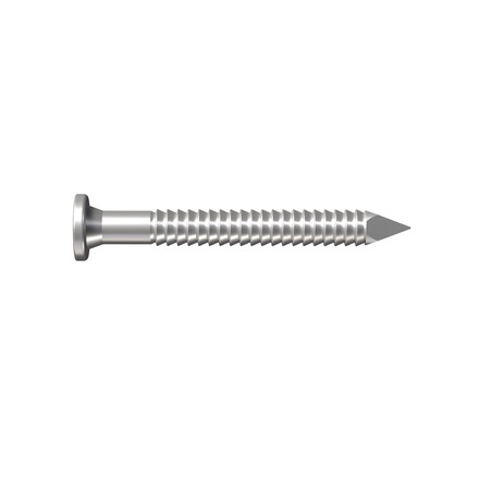
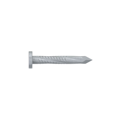
  • Use all specified fasteners: see “General Notes”.
  • Bend only once.
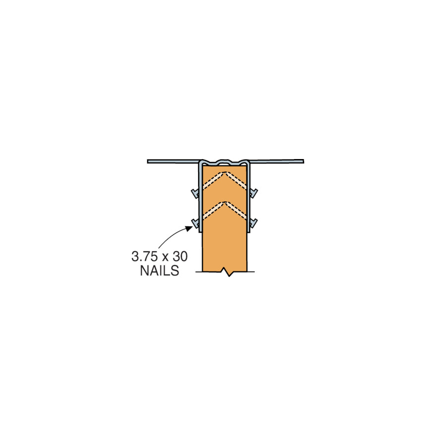
  • To ensure proper seat installation, install the bottom nails before the side nails.
  • Attach the sloped joist at both ends so the horizontal force developed by the slope is fully supported by the carried members. Web stiffeners are required with I-joists using this hanger style. For field skewing, see install sequence below.
  • Use all specified fasteners. See “General Notes”.
    Bend only once.
    To ensure proper seat installation, install the bottom nails before the side nails.
  • Attach the sloped joist at both ends so the horizontal force developed by the
    slope is fully supported by the carried members. Web stiffeners are required
    with I-joists using this hanger style. For field skewing, see install sequence below.
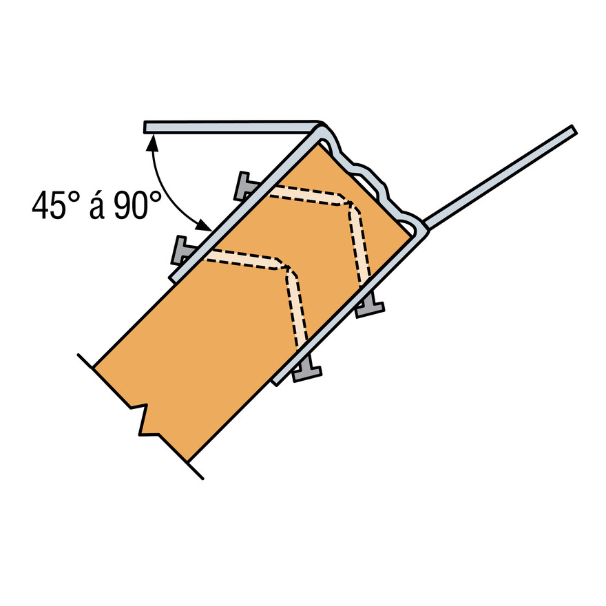
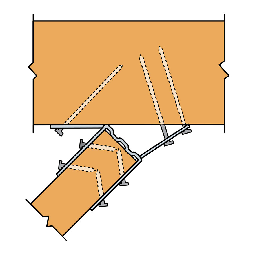
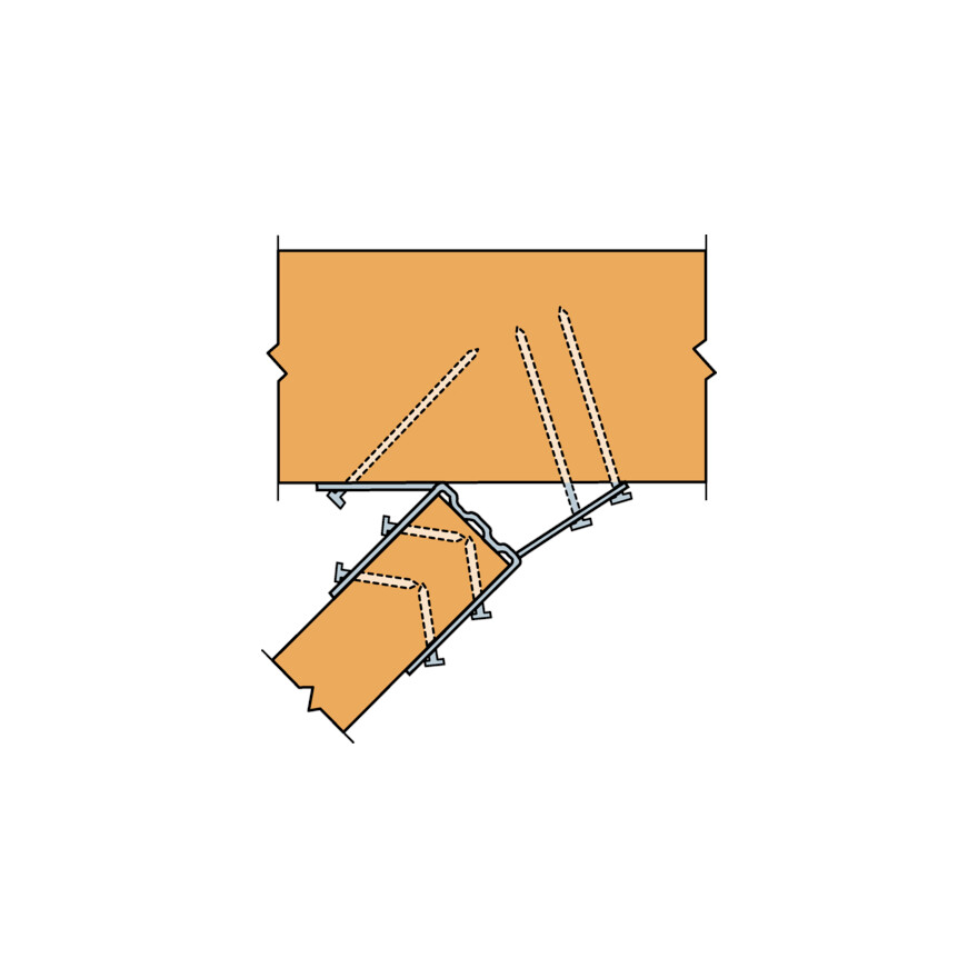
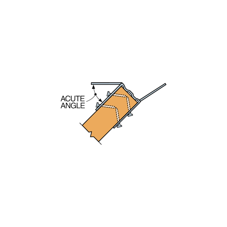
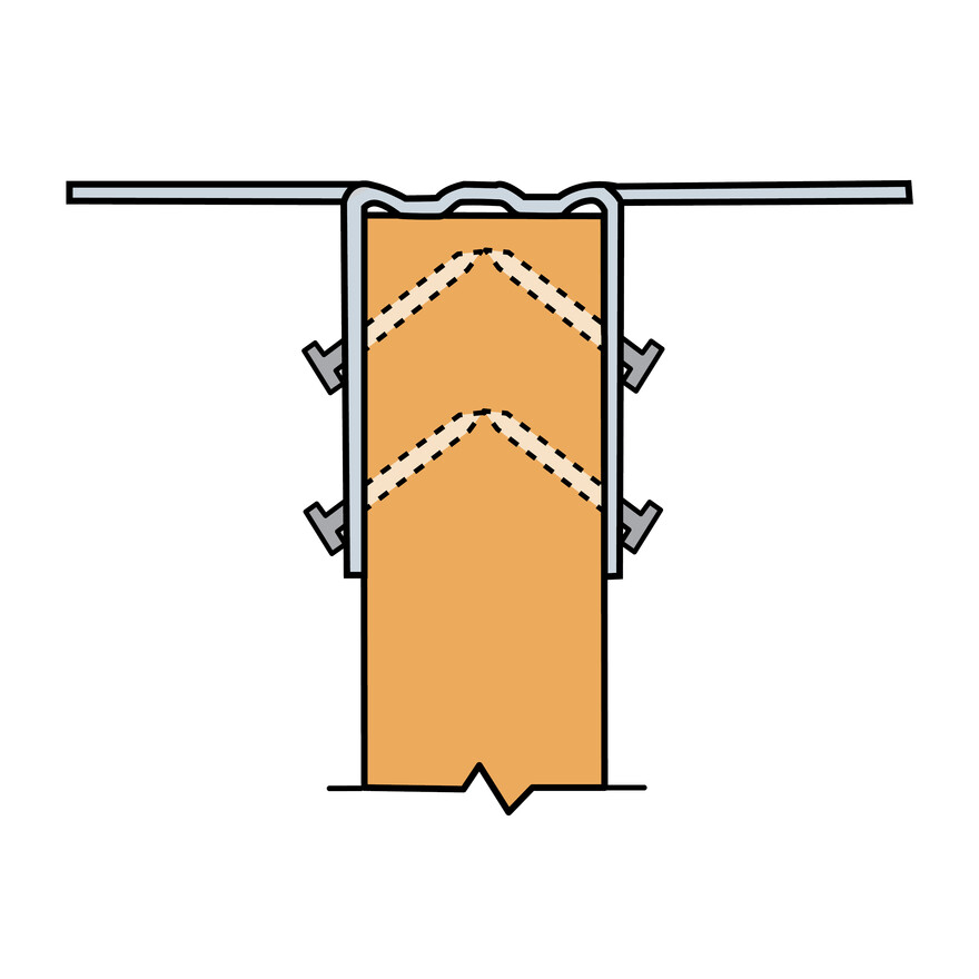
  • Skew flange to form acute angle. Bend other flange back along centre line of slots. Bend once only.
  • Attach hanger to the carrying member, acute angle side first, install nails at an angle. 

Certification

Declaration of Performance (DoP)

European Technical Assessment (ETA)

CAD and BIM Library

Buy from Distributor

No items available.

Contact

Simpson Strong-Tie Poland

Simpson Strong-Tie Sp. z o.o.

ul. Karczunkowska 42
02-871 Warszawa
Poland