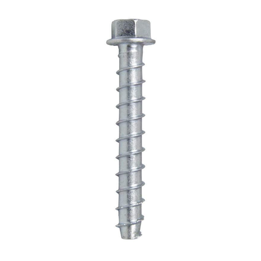
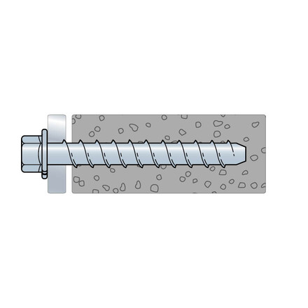
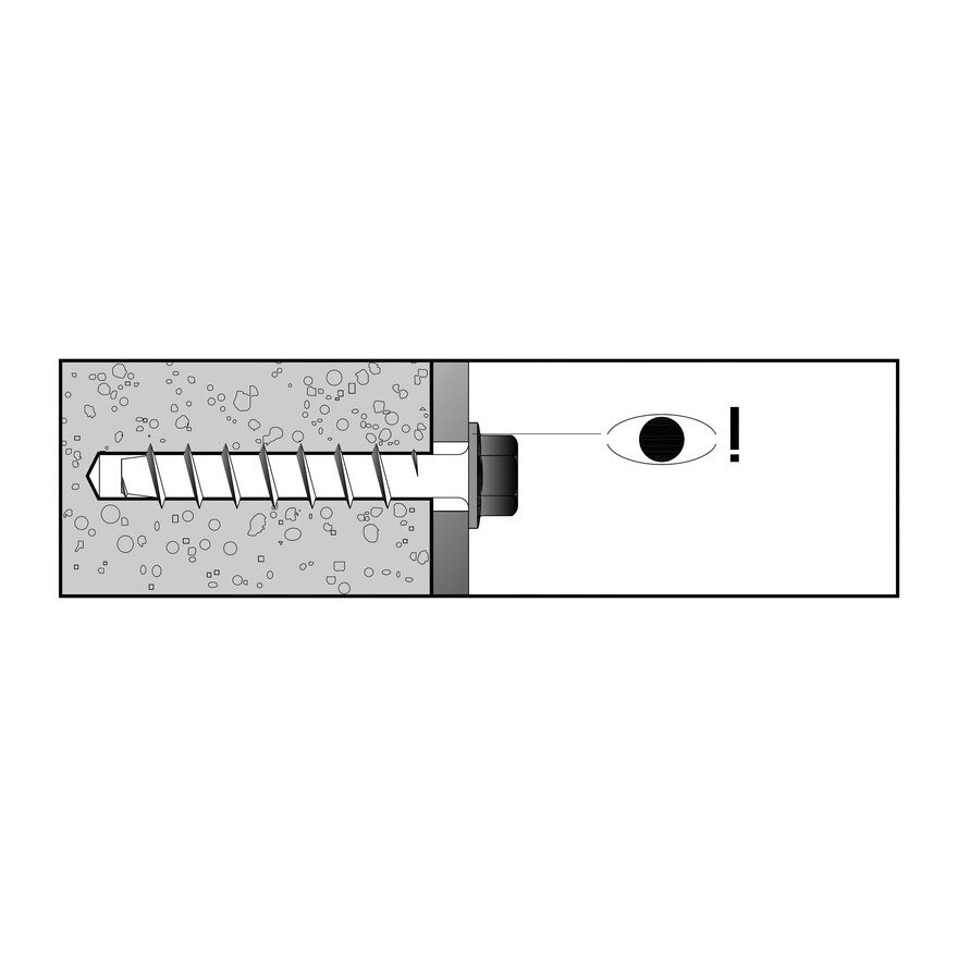
High capacity undercut anchor, concrete screw
Undecut anchor for heavy duty
Product Details
Features
Material
- Electro-galvanized steel
Benefits
- Quicker installation than expansion anchor
- aesthetic hexagonal head
- Large
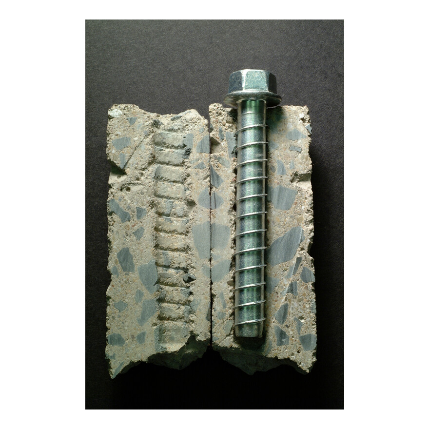
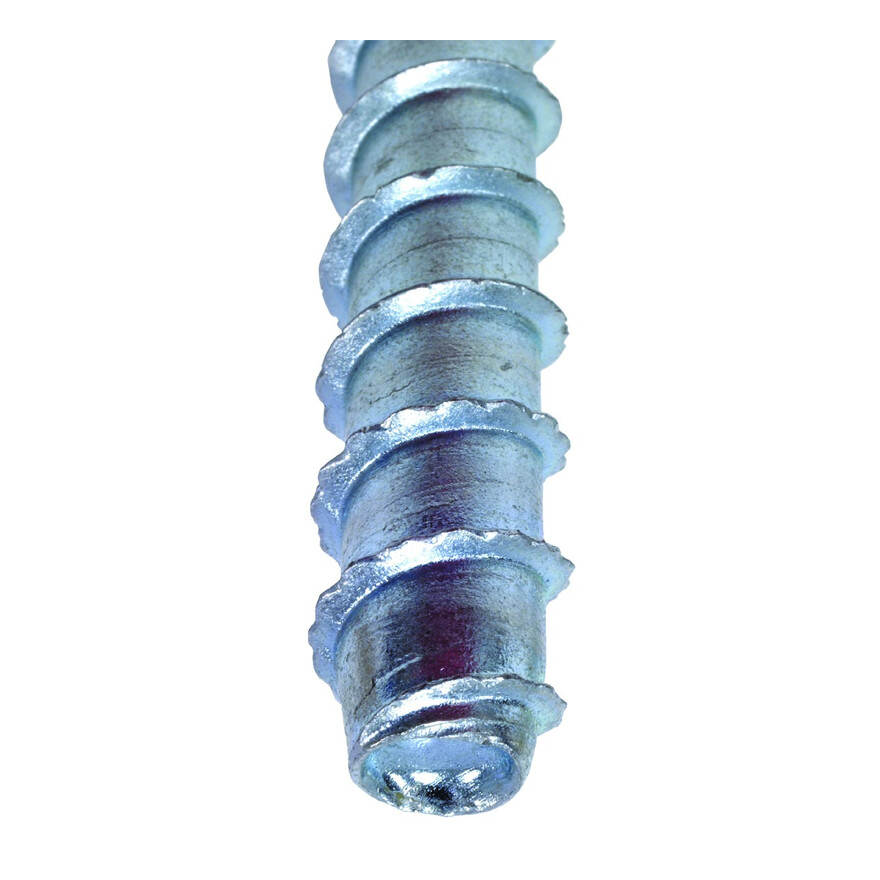
- Thread design undercuts to efficiently transfer the load to the base material
- Standard fractional sizes
- Specialized heat-treating process creates tip hardness for better cutting without compromising the ductility
- No special drill bit required — designed to install using standard-sized ANSI tolerance drill bits
- Testing shows the Titen HD® installs in concrete with 50% less torque than competitor anchors
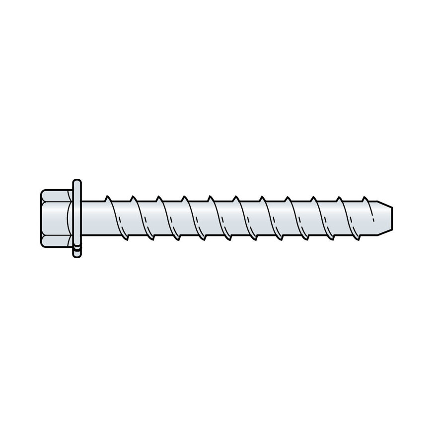
- Hex-washer head requires no separate washer and provides a clean installed appearance
- Removable — ideal for temporary anchoring (e.g., formwork, bracing) or applications where fixtures may need to be moved (reuse of the anchor to achieve listed load values is not recommended)
Application
Suitable On
- Cracked and uncracked concrete
Technical Data
Product Dimensions
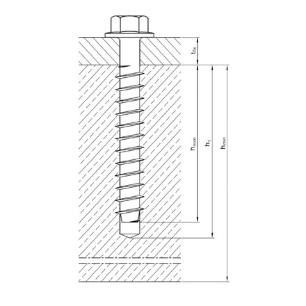
| References | Item Code | Ø Thread [mm] | Total Length [mm] | Max. Fixture Thickness [mm] | Maximum diameter of hole in the fixture [mm] | Ø drilling hole x min. drilling depth [mm] |
|---|---|---|---|---|---|---|
| THD M8-70/5 | THD08070 | 10.3 | 70 | 5 | 12 | 8 x 75 |
| THD M8-80/15 | THD08080 | 10.3 | 80 | 15 | 12 | 8 x 75 |
| THD M8-100/35 | THD08100 | 10.3 | 100 | 35 | 12 | 8 x 75 |
| THD M8-120/55 | THD08120 | 10.3 | 120 | 55 | 12 | 8 x 75 |
| THD M8-140/75 | THD08140 | 10.3 | 140 | 75 | 12 | 8 x 75 |
| THD M8-160/95 | THD08160 | 10.3 | 160 | 95 | 12 | 8 x 75 |
| THD M10-80/5 | THD10080 | 12.5 | 80 | 5 | 14 | 10 x 85 |
| THD M10-90/15 | THD10090 | 12.5 | 90 | 15 | 14 | 10 x 85 |
| THD M10-100/25 | THD10100 | 12.5 | 100 | 25 | 14 | 10 x 85 |
| THD M10-120/45 | THD10120 | 12.5 | 120 | 45 | 14 | 10 x 85 |
| THD M10-140/65 | THD10140 | 12.5 | 140 | 65 | 14 | 10 x 85 |
| THD M10-160/85 | THD10160 | 12.5 | 160 | 85 | 14 | 10 x 85 |
| THD M10-170/95 | THD10170 | 12.5 | 170 | 95 | 14 | 10 x 85 |
| THD M12-110/15 | THD12110 | 14.4 | 110 | 15 | 16 | 12 x 105 |
| THD M12-130/35 | THD12130 | 14.4 | 130 | 35 | 16 | 12 x 105 |
| THD M12-150/55 | THD12150 | 14.4 | 150 | 55 | 16 | 12 x 105 |
| THD M12-190/95 | THD12190 | 14.4 | 190 | 95 | 16 | 12 x 105 |
| THD M16-130/15 | THD16130 | 19.6 | 130 | 15 | 22 | 16 x 130 |
| THD M16-150/35 | THD16150 | 19.6 | 150 | 35 | 22 | 16 x 130 |
Design Resistance
| References | Design resistance | ||||||||||||||||
|---|---|---|---|---|---|---|---|---|---|---|---|---|---|---|---|---|---|
| Tension - NRd [kN] | Shear - VRd [kN] | Bending moment – MRd [Nm] | |||||||||||||||
| Cracked concrete | Non-cracked concrete | Cracked concrete | Non-cracked concrete | ||||||||||||||
| C20/25 | C30/37 | C40/50 | C50/60 | C20/25 | C30/37 | C40/50 | C50/60 | C20/25 | C30/37 | C40/50 | C50/60 | C20/25 | C30/37 | C40/50 | C50/60 | ||
| THD M8-70/5 | 3.3 | 4.1 | 4.7 | 5.2 | 4.2 | 5.1 | 5.9 | 6.5 | 11.7 | 11.7 | 11.7 | 11.7 | 11.7 | 11.7 | 11.7 | 11.7 | 26.7 |
| THD M8-80/15 | 3.3 | 4.1 | 4.7 | 5.2 | 4.2 | 5.1 | 5.9 | 6.5 | 11.7 | 11.7 | 11.7 | 11.7 | 11.7 | 11.7 | 11.7 | 11.7 | 26.7 |
| THD M8-100/35 | 3.3 | 4.1 | 4.7 | 5.2 | 4.2 | 5.1 | 5.9 | 6.5 | 11.7 | 11.7 | 11.7 | 11.7 | 11.7 | 11.7 | 11.7 | 11.7 | 26.7 |
| THD M8-120/55 | 3.3 | 4.1 | 4.7 | 5.2 | 4.2 | 5.1 | 5.9 | 6.5 | 11.7 | 11.7 | 11.7 | 11.7 | 11.7 | 11.7 | 11.7 | 11.7 | 26.7 |
| THD M8-140/75 | 3.3 | 4.1 | 4.7 | 5.2 | 4.2 | 5.1 | 5.9 | 6.5 | 11.7 | 11.7 | 11.7 | 11.7 | 11.7 | 11.7 | 11.7 | 11.7 | 26.7 |
| THD M8-160/95 | 3.3 | 4.1 | 4.7 | 5.2 | 4.2 | 5.1 | 5.9 | 6.5 | 11.7 | 11.7 | 11.7 | 11.7 | 11.7 | 11.7 | 11.7 | 11.7 | 26.7 |
| THD M10-80/5 | 4.2 | 5.1 | 5.9 | 6.5 | 5.8 | 7.1 | 8.2 | 9 | 18.3 | 18.3 | 18.3 | 18.3 | 18.3 | 18.3 | 18.3 | 18.3 | 52.7 |
| THD M10-90/15 | 4.2 | 5.1 | 5.9 | 6.5 | 5.8 | 7.1 | 8.2 | 9 | 18.3 | 18.3 | 18.3 | 18.3 | 18.3 | 18.3 | 18.3 | 18.3 | 52.7 |
| THD M10-100/25 | 4.2 | 5.1 | 5.9 | 6.5 | 5.8 | 7.1 | 8.2 | 9 | 18.3 | 18.3 | 18.3 | 18.3 | 18.3 | 18.3 | 18.3 | 18.3 | 52.7 |
| THD M10-120/45 | 4.2 | 5.1 | 5.9 | 6.5 | 5.8 | 7.1 | 8.2 | 9 | 18.3 | 18.3 | 18.3 | 18.3 | 18.3 | 18.3 | 18.3 | 18.3 | 52.7 |
| THD M10-140/65 | 4.2 | 5.1 | 5.9 | 6.5 | 5.8 | 7.1 | 8.2 | 9 | 18.3 | 18.3 | 18.3 | 18.3 | 18.3 | 18.3 | 18.3 | 18.3 | 52.7 |
| THD M10-160/85 | 4.2 | 5.1 | 5.9 | 6.5 | 5.8 | 7.1 | 8.2 | 9 | 18.3 | 18.3 | 18.3 | 18.3 | 18.3 | 18.3 | 18.3 | 18.3 | 52.7 |
| THD M10-170/95 | 4.2 | 5.1 | 5.9 | 6.5 | 5.8 | 7.1 | 8.2 | 9 | 18.3 | 18.3 | 18.3 | 18.3 | 18.3 | 18.3 | 18.3 | 18.3 | 52.7 |
| THD M12-110/15 | 6.7 | 8.1 | 9.4 | 10.3 | 13.9 | 16.9 | 19.6 | 21.5 | 25.2 | 25.2 | 25.2 | 25.2 | 25.2 | 25.2 | 25.2 | 25.2 | 85.3 |
| THD M12-130/35 | 6.7 | 8.1 | 9.4 | 10.3 | 13.9 | 16.9 | 19.6 | 21.5 | 25.2 | 25.2 | 25.2 | 25.2 | 25.2 | 25.2 | 25.2 | 25.2 | 85.3 |
| THD M12-150/55 | 6.7 | 8.1 | 9.4 | 10.3 | 13.9 | 16.9 | 19.6 | 21.5 | 25.2 | 25.2 | 25.2 | 25.2 | 25.2 | 25.2 | 25.2 | 25.2 | 85.3 |
| THD M12-190/95 | 6.7 | 8.1 | 9.4 | 10.3 | 13.9 | 16.9 | 19.6 | 21.5 | 25.2 | 25.2 | 25.2 | 25.2 | 25.2 | 25.2 | 25.2 | 25.2 | 85.3 |
| THD M16-130/15 | 13.9 | 16.9 | 19.6 | 21.5 | 16.7 | 20.3 | 23.5 | 25.8 | 38.3 | 46.7 | 46.7 | 46.7 | 46.7 | 46.7 | 46.7 | 46.7 | 214.9 |
| THD M16-150/35 | 13.9 | 16.9 | 19.6 | 21.5 | 16.7 | 20.3 | 23.5 | 25.8 | 46.7 | 46.7 | 46.7 | 46.7 | 46.7 | 46.7 | 46.7 | 46.7 | 214.9 |
1) The design resistances have been calculated using the partial safety factors for resistances stated in ETA-12/0060.
2) The recommended loads have been calculated using the partial safety factors for resistances stated in ETA-12/0060 and with a partial safety factor for actions of
γF=1.4.
3) The load figures are valid for unreinforced concrete and reinforced concrete with a rebar spacing s ≥ 15 cm (any diameter) or with a rebar spacing s ≥ 10 cm, if
the rebar diameter is 10 mm or smaller.
4) “For combined tension and shear loads or anchor groups and/or in case of edge influence, a calculation per ETAG 001, Annex C, design method A or according to
CEN/TS 1992-4:2009 design method A shall be performed. Anchors under fire exposures are to be designed in accordance with EOTA -TR 020:2004 or CEN/TS 1992-4:2009 Annex D.
For details see ETA-12/0060.
Installation
Installation
Installation
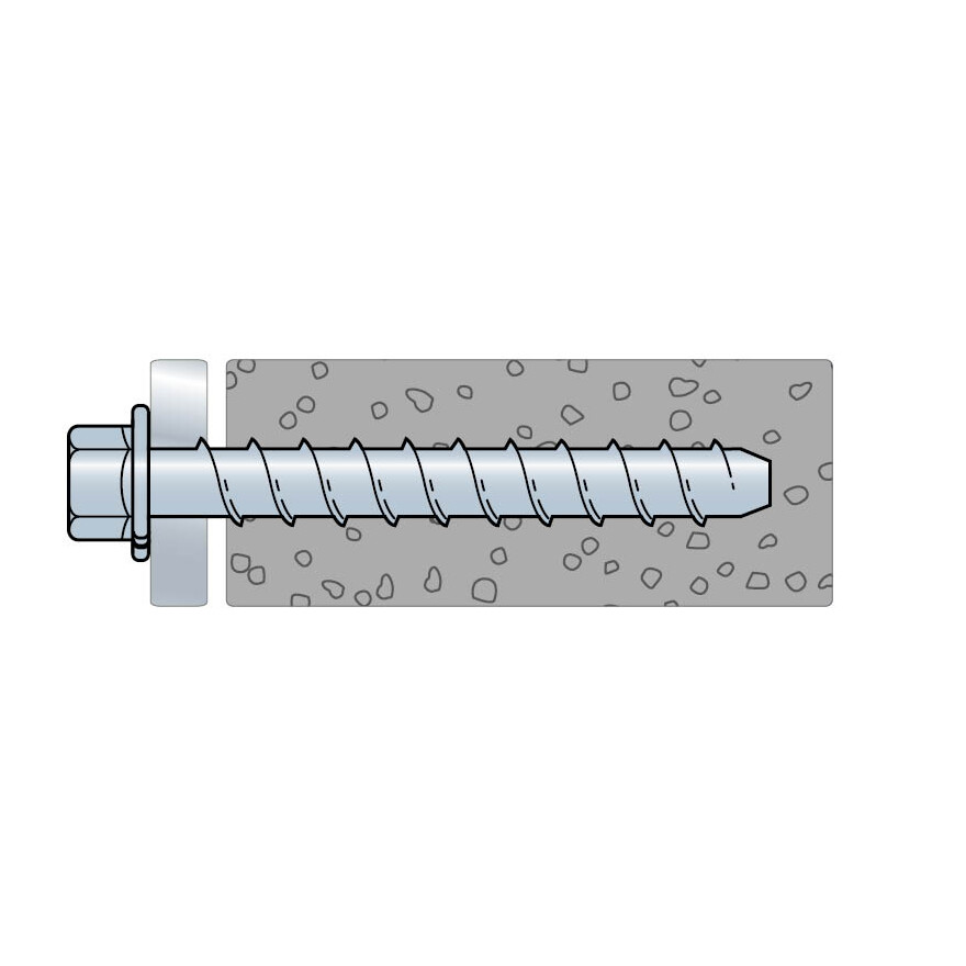
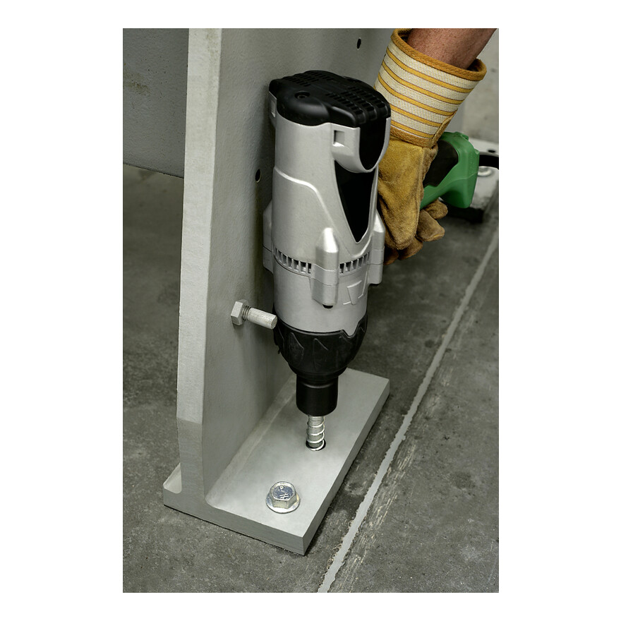
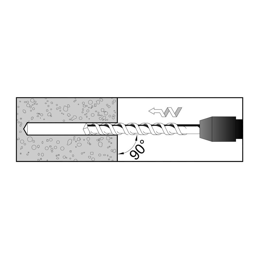
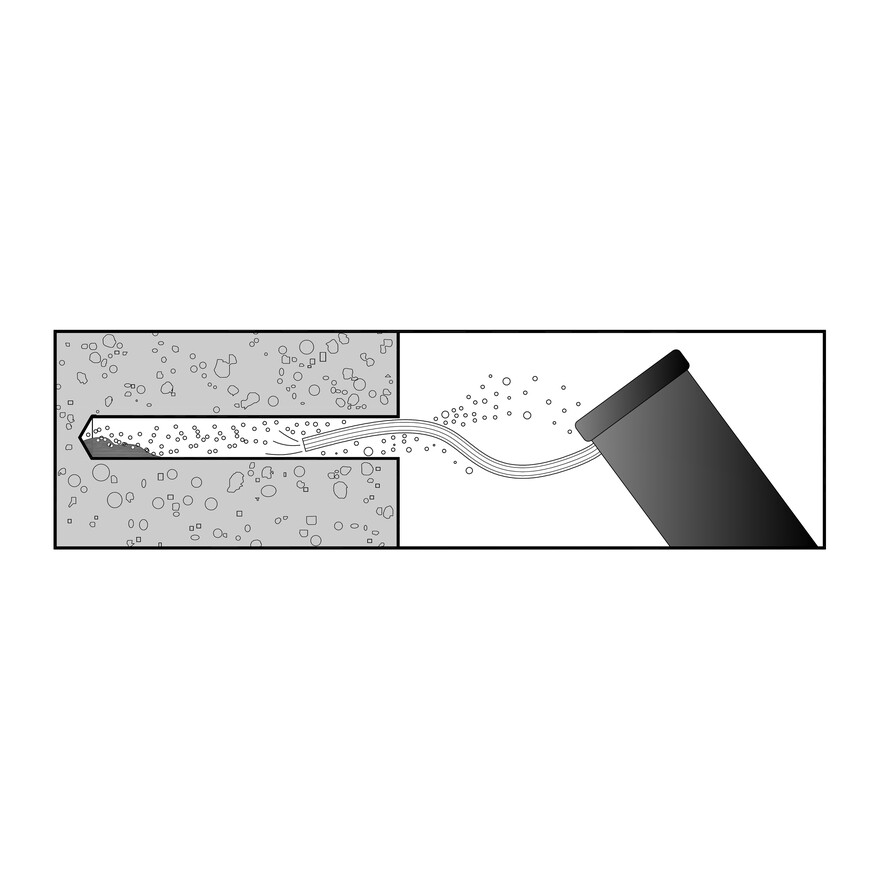
- Drill a hole in the base material using a carbide drill bit the same diameter as the nominal diameter of the anchor to be installed. Drill the hole to the specified embedment depth plus minimum hole depth overall (see table below right) to allow the thread tapping dust to settle, and blow it clean using compressed air. (Overhead installations need not be blown clean.) Alternatively, drill the hole deep enough to accommodate embedment depth and the dust from drilling and tapping.
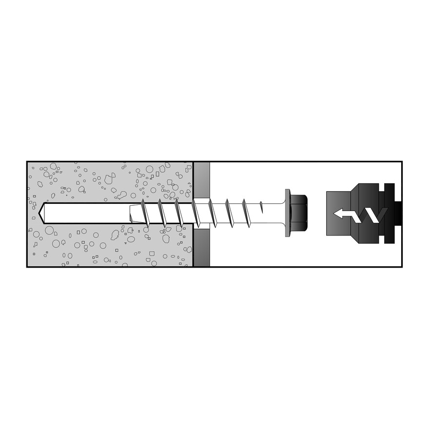
- Insert the anchor through the fixture and into the hole.
- Tighten the anchor into the base material until the hex-washer head contacts the fixture.
