


Quik Drive® System Features
Image
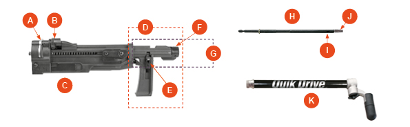
- A-Locking Lever
- B-Depth Adjustment Wheel
- C-Bit Release Key
- D-Nose Piece
- E-Feed Pawl Lever
- F-Nose
- G-Guide Tube
- H-Mandrel
- I-Bit Release Slot
- J-Bit
- K-Extension
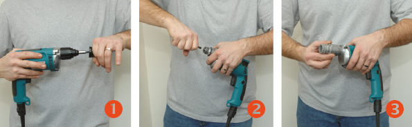
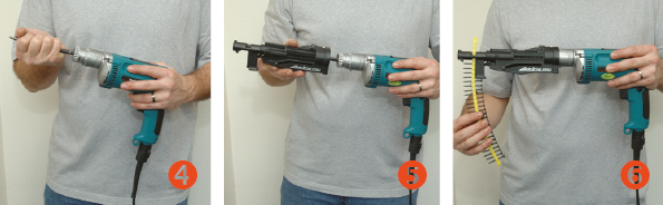
The Quik Drive® series of attachments are compatible with most leading power tools and can be installed with just a few steps, so you can be up and running in seconds.
Installation:
- Pull off the depth stop cap of your drywall screwgun and remove all circlips
- Pull out the bit holder of the screwgun
- Mount the correct adapter onto the screwgun and tighten (you may require an allen key, supplied)
- Insert the Quik Drive® bit holder (Mandrel) into the screwgun
- Insert the attachment over the Mandrel and onto the adapter, clicking it into place
- Insert the screw strip, with the pointed tip first, into the nose piece on the attachment
- The Quik Drive® system is ready to use
Image
Image
Quik Drive® Troubleshooting Guide
| Symptom | Solution |
|---|---|
| Screws won't drive. They spin for a second, then lay over on their side. | Make sure the screw gun is not set to reverse. Make sure the screws are being driven straight. |
| Screws won't drive completely. They go down about halfway, then the bit spins out. | Check that you are using the correct bit for the type of screws you are using or if the bit is worn. Replace in either case. Keep constant pressure on when driving the screws. |
| Screws won't drive completely. They are almost completely driven but won't countersink fully. | Check the depth adjustment on the attachment and reset if necessary. You may have missed the substrate. For example in a flooring installation you may have missed the joist. Check that all cir-clips and rings have been removed from the front of the driver before the adapter is fitted. |
| Screws don't advance properly causing the the tool to jam. | Use only Simpson Strong-Tie® Quik Drive® screws. Make sure the screw strip is inserted correctly - pointed end first. Lift the tool completely off the work surface after driving each screw. Don't drag the screw strips on the work surface as you move. Be sure that the feed pawl assembly is intact and the feed lever engaged. |
Self-Drilling Screw Troubleshooting Guide
| Failure Mode | Likely Cause(s) | Suggested Action |
|---|---|---|
| Split at point (web) | Excessive force (feed) applied while drilling | Reduce application force |
| Outer corners worn or melted | Drill RPM (cutting speed) too high | Use slower motor or partial trigger pull |
| Cutting edges chipping or breaking | Excessive force (feed) applied while drilling | Reduce application force |
| Point melted or diameter significantly reduced |
|
|
| Screw spins without drilling a hole |
|
|