


Theory of concrete design
Concrete as a building material has very good compression resistance, but around ten times less resistance for tension. In the design process in general the tension resistance of concrete is ignored. The theory of concrete structures reinforced with steel bars is based on the assumption the all the tension is resisted by the steel bars. For that reason, in the zones of the concrete elements where tension appears, steel bars need to be used to take the tesion load.
Definition of cracked and non-cracked concrete
Cracked and non-cracked concrete terms are not related to the age of the structure or any defects of concrete surface or cracks and gaps in the concrete due to corrosion of concrete.
Basically, cracked concrete can be identified with the tension zone and non-cracked concrete with the compression zone of the concrete element.
Cracking of concrete element in the tension zone is natural process and is a result of low resistance for tension of concrete as a material. In most of the cases cracks with width not exciding 0,4mm don’t have negative influence on the load-carrying capacity and durability of the structure.
In typical bent elements models (simply supported beams loaded downward) tension zone is the bottom part of the element. But this is not a general rule, there might appear some models or loads that will cause tension zone in the top part of the element. Some examples are shown on the pictures. When identifying the tension and compression zone isn’t easy, the worst case scenario should be taken under further consideration – tension zone (cracked concrete) or the designer should analyze the situation according to ETAG 001, annex C, p.4.1.
Concrete can be treated as non-cracked if the following formula is true: L + R < 0
σL - Stresses in the concrete due to external loads, including those applied by the fastener
σR - Stresses in the concrete due to intrinsic imposed deformations (such as shrinkage) or extrinsic imposed deformations (such as displacement of supporting members of structure, thermal expansion/contraction, etc.). In the absence of a detailed analysis, EN 1992-4 suggests = 3MPa (according to EC2).
Load Direction
- Anchor capacity stated for all load directions (options 1 and 2 for cracked concrete and options 7 and 8 for non-cracked concrete)
- Stated capacity value related to all load directions (options 3 to 6 for cracked concrete and options 9 to 12 for non-cracked concrete)
Anchor Spacing and Edge Distance
- Tested both characteristic and minimum spacing scr and smin. Tested both characteristic and minimum Edge distance ccr and cmin (options 1 to 4 for cracked concrete and options 7 to 10 for non-cracked concrete). For design process it allows to interpolate the anchor capacity for different spacing and edge distance according to design method.
- If the characteristic spacing and characteristic edge distance are the only values stated, then. Those values should be treated as minimum. (options 5 and 6 for cracked concrete and options 11 and 12 for non-cracked concrete).
Anchor load-carrying capacity
Anchor load-carrying capacities published in the following catalogue are design capacities (NRd, VRd) including partial safety factors, material safety factors for anchors which values are stated in the relevant ETA. Those safety factors relates the particular product and have been assessed during certification and testing. Capacities refers to non-reinforced concrete and reinforced concrete with bars at spacing s ≥15cm for any bar diameter or at spacing s ≥10cm if the bar diameter is 10mm or less. Shear capacity is stated for a single anchor without edge distance reduction. For the anchorage close to the edge (c ≤ max{10hef; 60d}) it is designer responsibility to check the ETAG001 pry-out failure mechanism according to annex C, design method A. If the distances between the anchors in the group are smaller than the characteristic values (i.e. ≤ scr, M and/or c ≤ ccr,N) designer needs to follow the calculation according to ETAG 001, annex C, design method A or run the calculation using Simpson Strong-Tie Anchor Designer software.
Minimum spacing and edge distance
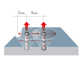
Distance between anchors in the group and Edge distance is less than characteristic values scr, ccr. Full stress cones in the concrete cannot be created and anchors will not reach full capacity. In such a cases it is recommended to design connection using our free Anchor Designer software.
Characteristic spacing and edge distance
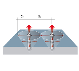
Distance between the anchors in the group is at least equal to the characteristic spacing scr. Distance between the each anchor and the concrete edge is at least equal to the characteristic edge distance ccr. Full stress cones in the concrete can be created and anchors can reach full capacity.